








Cryogenic Liquid Storage Tank Design and Engineering Principles
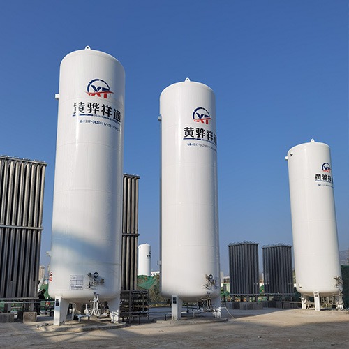
Storing liquefied gases at extremely low temperatures presents a unique set of engineering challenges that go far beyond what conventional storage systems require. Whether the application involves liquefied natural gas at minus 162 degrees Celsius, liquid oxygen sitting at minus 183 degrees, or liquid nitrogen hovering around minus 196 degrees, the fundamental physics at play demand careful attention during every phase of design and construction. For any facility relying on bulk cryogenic storage, working with an experienced storage tank manufacturer can mean the difference between decades of reliable operation and chronic operational headaches.

Understanding Thermal Stratification and Boil-Off Dynamics
One of the first things a competent engineer considers when designing a cryogenic liquid storage system is the behavior of the stored fluid over time. Even with high-performance insulation, heat leaks into the tank gradually. This heat ingress causes a small fraction of the liquid to vaporize, a phenomenon known as boil-off gas. In a well-designed vertical storage tank, boil-off rates typically range from 0.1 to 0.5 percent per day, depending on tank size, insulation quality, and ambient conditions. Thermal stratification compounds this issue: warmer liquid tends to settle at the top of the tank while colder, denser liquid remains at the bottom, creating temperature gradients that accelerate localized boiling and increase internal pressure. Engineers address this through bottom filling designs, proper venting systems, and in some cases, automated mixing pumps that circulate the liquid to prevent dangerous stratification buildup.
Material Selection for Cryogenic Service
Most structural steels become dangerously brittle when exposed to temperatures below minus 40 degrees. That is why cryogenic storage tank construction relies almost exclusively on metals that retain toughness at extreme cold. Austenitic stainless steel grades such as 304L and 316L dominate the inner vessel market because their face-centered cubic crystal structure prevents the ductile-to-brittle transition that plagues carbon steels. For larger tanks where stainless steel becomes cost-prohibitive, nine percent nickel steel offers an excellent middle ground, maintaining adequate impact strength down to minus 196 degrees while keeping material costs manageable. Aluminum alloys like 5083 are another option, particularly favored in transport applications where weight savings matter. A reputable tank factory will conduct Charpy V-notch impact testing on every heat of steel received, verifying that the material meets the minimum absorbed energy requirements specified by the applicable design code before any cutting or welding begins.
Insulation Systems and Their Engineering Trade-offs
The insulation system is arguably the single most important subsystem in a cryogenic storage tank, directly dictating boil-off rates, operating costs, and the frequency of pressure relief events. Three primary approaches dominate the industry. Perlite-based insulation, the most common choice for large stationary tanks, involves filling the annular space between the inner and outer vessels with expanded perlite granules and maintaining a vacuum to eliminate convective heat transfer. This approach offers a good balance of cost and performance, typically achieving thermal conductivities in the range of 0.025 to 0.04 watts per meter-kelvin. High-vacuum multilayer insulation, sometimes called superinsulation, consists of dozens of alternating layers of reflective aluminum foil and low-conductivity spacer material, all housed within a hard vacuum of less than 0.001 pascals. This method achieves superior thermal performance but comes at a significantly higher manufacturing cost and is more vulnerable to vacuum degradation over time. Foam insulation, usually polyurethane or polystyrene, provides the lowest upfront cost but delivers the highest thermal conductivity, making it suitable only for applications where boil-off tolerance is generous.
Pressure Management and Relief System Design
Every cryogenic tank operates within a defined pressure envelope, and the pressure relief system serves as the last line of defense against over-pressurization. Designing this system correctly requires a thorough understanding of the worst-case scenarios the tank might experience, including external fire exposure, failure of the normal venting path, and maximum fill rate with all outlets blocked. The sizing of pressure relief valves follows strict rules laid out in codes such as the ASME Boiler and Pressure Vessel Code Section VIII and NFPA 59A. Beyond the relief valves themselves, engineers must specify appropriately sized vent stacks, ensure that discharge locations do not create asphyxiation hazards for personnel, and provide means to safely recover or flare vented gas. A qualified manufacturer will also incorporate redundant pilot-operated relief valves with remote monitoring capability, allowing plant operators to track relief events in real time and schedule maintenance before a small problem escalates into a costly shutdown.
Foundation Design and Ground Heat Flux Considerations
The foundation beneath a cryogenic storage tank faces a threat that ordinary concrete pads never encounter: the soil itself can freeze if enough cold penetrates downward through the base. Frozen ground expands, which can lift the tank unevenly and create dangerous stress concentrations in the shell. Engineers combat this through several proven strategies. Elevated foundations with air space beneath the tank cut off the direct conductive path to the ground. Heated concrete foundations embed electric heating cables or circulating warm fluid loops within the slab, actively replacing the heat that the tank removes. In locations with naturally warm ground temperatures, simple thick insulation layers beneath the tank base may suffice. The choice among these approaches depends on local climate, groundwater level, soil bearing capacity, and the specific operating temperature of the stored product. Working with a storage tank supplier who understands these geotechnical interactions helps ensure that the foundation design matches the demands of the installation site.
Conclusion
Designing a cryogenic liquid storage tank is a multidisciplinary exercise that draws on thermodynamics, materials science, structural engineering, and process safety. From the initial selection of cryogenic-grade materials through the detailed sizing of insulation systems, pressure relief devices, and foundations, each decision carries long-term implications for safety, efficiency, and operating cost. Partnering with a manufacturer that combines deep engineering expertise with rigorous quality control practices provides the best path to a storage system that performs reliably throughout its intended service life.
References
ASME Boiler and Pressure Vessel Code, Section VIII, Division 1, 2023 Edition
NFPA 59A: Standard for the Production, Storage, and Handling of Liquefied Natural Gas, 2022 Edition
API 620: Design and Construction of Large, Welded, Low-Pressure Storage Tanks, 13th Edition
ASHRAE Handbook, Fundamentals, 2021 Edition, Chapter on Cryogenics
CGA S-1.1: Pressure Relief Device Standards, Compressed Gas Association, 2019