








Cryogenic Tank Valves, Pressure Relief Devices, and Accessories: A Complete Guide
What You Cannot See Is What Can Kill You
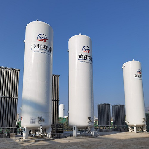
A cryogenic tank looks simple from the outside — a large cylindrical pressure vessel on support legs, with some pipes and gauges at one end. The complexity is inside the valve cabinet at that one end, where a dozen or more specialized valves and instruments manage the pressure, level, and flow of the cryogenic liquid inside. These components are the nervous system and immune system of the tank — and they are where most of the failure modes that matter live.
Most operators interact with these valves and instruments daily: opening and closing valves to fill and discharge the tank, reading the pressure gauge to check tank status, monitoring the level gauge to know how much product is in the tank. Understanding what these components do and how they work together is not just engineering trivia — it is the practical knowledge that separates a competent operator from one who does not know why the pressure alarm is going off at 2 AM.
The Critical Safety Devices
Pressure Relief Valve (PRV)
The most important safety device on the tank. A spring-loaded valve calibrated to open at the tank's design working pressure — for example, 1.6 MPa for a 1.6 MPa rated LNG tank. When tank pressure reaches the set pressure, the spring compresses and the valve opens, discharging gas to atmosphere. Once pressure drops back below the set pressure, the spring reseats and the valve closes. Set pressure is factory-calibrated and must not be adjusted in the field without a valid reason and proper documentation. PRVs must be removed and sent to a qualified test facility for periodic testing (typically annually).
Thermal Pressure Relief Device (TPRD)
A fusible plug or thermal fuse that melts at a specific temperature (typically 99°C or 110°C for cryogenic tanks). Unlike a PRV, which responds to pressure, a TPRD responds to temperature — specifically, it is the protection against external fire exposure. If a fire surrounds the tank, the TPRD melts or fuses open at the set temperature, creating a full-bore opening that allows rapid pressure relief. TPRD discharge must be routed to a safe location away from personnel and other equipment. The TPRD is a one-time device — it must be replaced after any fire event or if it has been activated.
Rupture Disc / Burst Disc
A thin metal membrane installed in a holder in the tank piping. The disc ruptures at a predetermined burst pressure — typically set at 100–110% of the PRV set pressure. Rupture discs provide overpressure protection where a PRV alone would be too slow or too small to handle the full-flow scenario. In cryogenic tank applications, rupture discs are often installed in series with PRVs to protect the tank during fire scenarios where a PRV might be impaired by flame impingement. After rupture, the disc must be replaced — this is a non-reclosing device.
Emergency Shutdown (ESD) Valve
An actuated shutoff valve (typically pneumatically or electrically actuated) installed in the liquid and vapor piping that can be rapidly closed from the control room or from a local emergency stop button. The ESD valve provides the means to isolate the tank from downstream piping in an emergency — a leak in the discharge line, a fire in the pump area, or any other scenario requiring immediate product isolation. ESD valves are typically spring-return (fail-safe closed) — if air or power is lost, the valve automatically closes.
Operating Valves and Instruments
| Component | Type | Function | Key Operating Note |
|---|---|---|---|
| Liquid Phase Valve | Globe or ball valve | Controls flow of liquid product in/out of tank | Open during filling/discharge; closed when tank is idle |
| Vapor Phase Valve | Globe or ball valve | Controls vapor space pressure during filling; equalizes pressure with supply tank | Must be open during filling to allow vapor to escape as liquid enters |
| Pressure Gauge | Bourdon tube or electronic | Displays current tank pressure; primary operational monitoring instrument | Normal range: 0.3–1.0 MPa for a 1.6 MPa tank; alarm if above 1.3 MPa |
| Level Gauge | Float type or differential pressure type | Indicates how much product is in the tank (as % of capacity) | High-level alarm at 85–90% fill; do not overfill |
| Thermocouple Vacuum Gauge | Instrumentation | Monitors insulation vacuum quality; detects insulation degradation early | If vacuum reading rises significantly, insulation may be degrading |
| Safety Valve Test Connection | Test tee with plugged connection | Allows PRV to be removed for testing without depressurizing the tank | Test connection must be isolated and capped when not in use |
Pressure Relief Valve Set Points: How They Are Determined
The pressure relief valve set point is determined by the tank's design working pressure and must comply with the pressure vessel code under which the tank was constructed (ASME Section VIII, EN 13458, GB/T 150, etc.). The relationship between design pressure and PRV set point is defined in the code and is non-negotiable.
Why Vacuum Monitoring Is Your Early Warning System
The thermocouple vacuum gauge is one of the most underappreciated instruments on a cryogenic tank. It measures the pressure in the vacuum space between the inner and outer tank. A healthy vacuum space has a pressure in the range of 10⁻³ to 10⁻⁶ Pa. As the vacuum degrades — due to micro-leaks, perlite outgassing, or adsorption saturation — the pressure rises.
Early detection of vacuum degradation through regular monitoring allows the operator to plan for tank refurbishment before the insulation performance deteriorates to the point where the tank pressure is frequently reaching the PRV set point during normal operation. Without monitoring, the first sign of vacuum degradation is often the PRV lifting frequently — by which point the insulation is already significantly compromised.
Filling Operations: Valve Sequencing
Proper valve sequencing during filling is critical for safety and to avoid tank overpressure. The basic sequence for filling a cryogenic tank from an LNG tanker is:
Verify tank pressure is at working pressure (0.3–0.8 MPa typically) before starting fill
Open the vapor phase valve (tank) to allow vapor to escape as liquid enters — this prevents pressure buildup
Open the liquid phase valve (tank) and the liquid discharge valve (tanker)
Begin filling slowly — rapid filling causes excessive vaporization and pressure spikes
Monitor pressure gauge throughout filling — pressure should remain stable; a rising pressure indicates a problem
Monitor the level gauge — stop filling when level reaches 85–90% (never fill to 90%)
Close liquid phase valve, then vapor phase valve on the tank
Close tanker discharge valve
Disconnect the cryogenic hose only after all pressure has equalized between hose and tanker
Frequently Asked Questions
The PRV is the single most important safety device. When insulation degrades and cryogenic liquid vaporizes faster than normal, pressure rises. If it exceeds the tank's design pressure, catastrophic failure becomes possible. The PRV opens at the set pressure (typically equal to the design working pressure) and discharges gas to atmosphere, relieving the overpressure before it reaches dangerous levels. Never block, adjust, or remove a PRV.
A safety valve opens rapidly (pop action) for compressible gas service; a relief valve opens gradually in proportion to pressure rise. A safety relief valve combines both — it opens gradually for small overpressures but pops open for large overpressure events. Most cryogenic tanks use safety relief valves. In practice, the terms are used interchangeably in the industry.
Heat ingress through the insulation causes slow vaporization of the cryogenic liquid. A well-maintained 50m³ LNG tank generates 20–25 kg of boil-off gas per day under normal conditions. Pressure also rises during filling, especially if filling too fast or with warmer-than-normal product. A rising pressure during idle storage is the primary indicator of insulation degradation.
A rupture disc is a thin metal membrane that ruptures at a predetermined pressure — a one-time device unlike a resealing PRV. It is used in high-flow applications or as a backup to a PRV, particularly for fire scenarios where flame impingement might impair a PRV's performance. After rupturing, it must be replaced before the tank can be returned to service.
PRVs must be re-tested and re-set by qualified personnel annually. Rupture discs must be replaced at manufacturer-specified intervals (typically every 1–5 years) or after any actuation event. Routine visual inspection of valves and piping should be monthly. Vacuum monitoring via thermocouple vacuum gauge should be checked monthly to detect insulation degradation early. Periodic pressure vessel inspection (TSG 21 / ASME Section VIII) typically occurs every 5 years.